Today you'll build two circuits on the breadboard, using the CD4069UBE hex inverter — a $0.50 digital logic chip that, biased into its linear region, becomes a surprisingly musical audio distortion stage:
Build 1 — CMOS Preamp: one inverter wrapped in feedback makes a warm gain/soft-clip stage.
Build 2 — Schmitt Fuzz: two more inverters added after the preamp turn the signal into a gated square wave.
Both circuits are built on the same breadboard — Build 2 adds components to Build 1 without tearing anything down. The breadboard diagrams are your primary reference; the schematics are there for when you want to see why.
What to submit:
An Audacity project, or exported WAV files plus screenshots.
Three labeled recordings:
→ preamp-clean
→ preamp-cranked
→ schmitt-fuzz
One Plot Spectrum screenshot for each recording.
This completed worksheet.
Reference
Parasit Studio — CMOS Workshop (original source): parasitstudio.com/resources/cmosworkshop/. Local copy: CMOSworkshop.pdf in your course folder — Part 1 & Part 2 are today's builds.
Software simulator (compare your breadboard to the model):fuzzbox-cmos.html
Parts & Tools
Breadboard with +9 V supply
CD4069UBE hex inverter ×1
1 MΩ resistor ×3
100 kΩ linear pot ×1 (output volume)
100 kΩ linear pot ×1 (Schmitt hysteresis)
1 MΩ linear pot ×1 (preamp gain — optional, can use fixed 1 MΩ)
100 nF capacitor ×2 (marked 104)
470 pF capacitor ×1 (marked 471, optional)
1/4" input jack + cable (guitar) or 3.5 mm plug (computer)
Output → computer line-in (Audacity)
Dupont jumpers, alligator clips, multimeter
CMOS handling: 4069UBE inputs are extremely high-impedance. Touch a grounded object before picking the chip up. Orient the notch toward the left side of the board so pin 1 is upper-left.
Important — unused CMOS inputs: Any input pin you are not actively driving must be connected to either GND or +9 V. Never leave a CMOS input floating, or the circuit may become noisy or unstable. On a 4069UBE the inputs are pins 1, 3, 5, 9, 11, 13 — ground any of these you aren't using.
Part 1
Know Your Chip (2 minutes)
Read & label
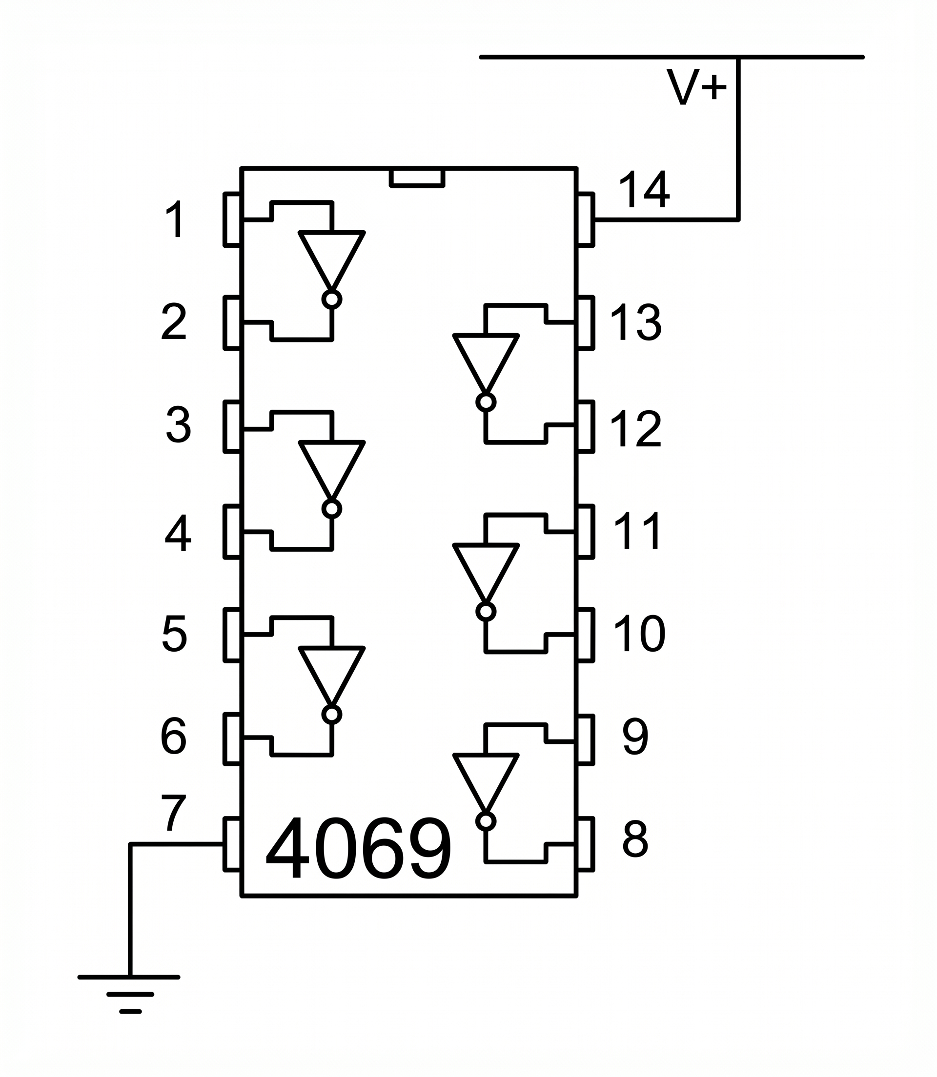
The CD4069UBE contains six identical inverter gates. Today you'll use three of them in the main build: one for the preamp (Build 1) and two more for the Schmitt trigger (Build 2). A fourth inverter is used only in the optional cascade variant (Part 4). Pin 14 is power, pin 7 is ground.
A CMOS inverter's transfer curve is a soft S around VDD/2. That middle "linear" region is what we exploit: biased at the center of the S, a small AC signal comes out inverted and amplified. Push too hard and it clips into the rails — that's the fuzz.
The self-bias trick: a 1 MΩ resistor from output back to input pulls the inverter to its midpoint automatically, so the gate biases itself near VDD/2. That puts it in the inverter's linear region, where it can amplify small audio signals. No reference voltage, no divider — the chip biases itself.
This only works with the UB (unbuffered) version of the chip, because only UB has a smooth S-curve. The buffered CD4069 (no UB suffix) has a near-step transfer curve and is useless as a preamp.
Q.
Before you start building: with VDD = 9 V, roughly what DC voltage should you measure at the output of a self-biased inverter with no signal applied? Explain briefly. (You'll verify the number in Part 2.)
Prediction + explanation
Part 2
Build 1 — CMOS Preamp
Breadboard + Audacity
Goal: wire one CD4069UBE inverter as a self-biased audio preamp. Clean-ish at low gain, soft-clip distortion at high gain. This is the foundation for Build 2.
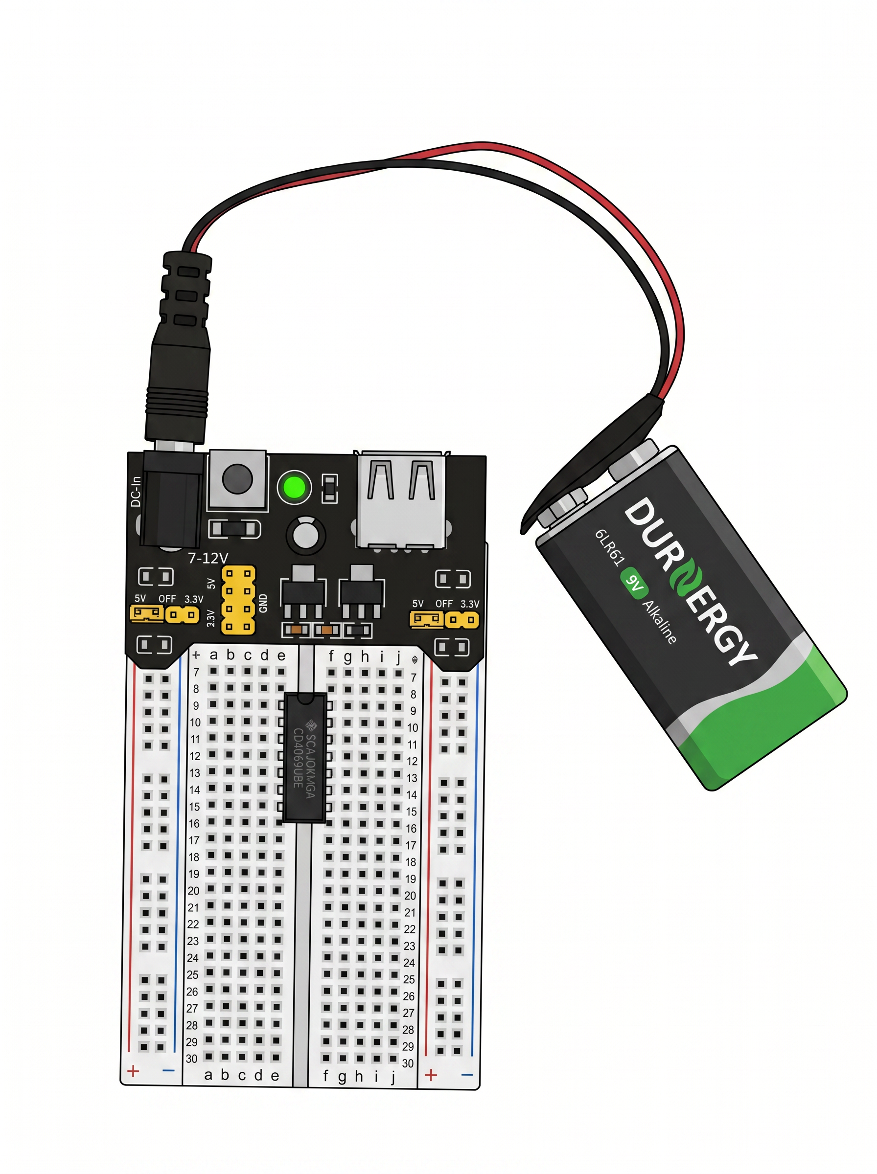
Start here: power-supply module plugged into the breadboard, 9 V battery connected to the barrel jack, and the CD4069UBE seated across the center channel (notch on the left). No resistors or caps yet. Confirm +9 V on the red rail and GND on the blue rail with a multimeter before you go further.
Start here — breadboard power-supply module (set to 9 V / VIN) fed by the 9 V battery, CD4069UBE seated with the notch on the left. Nothing else wired yet.
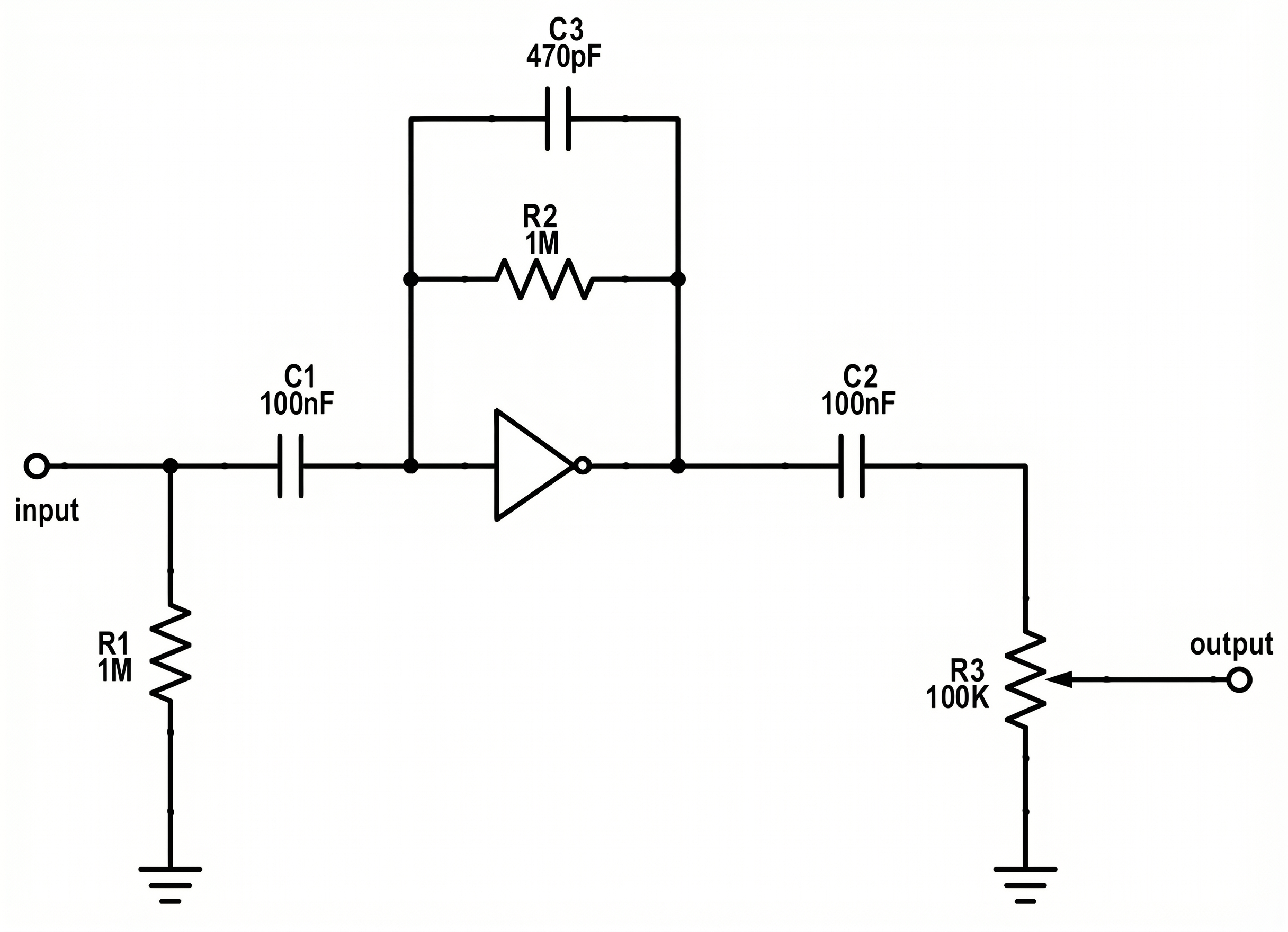
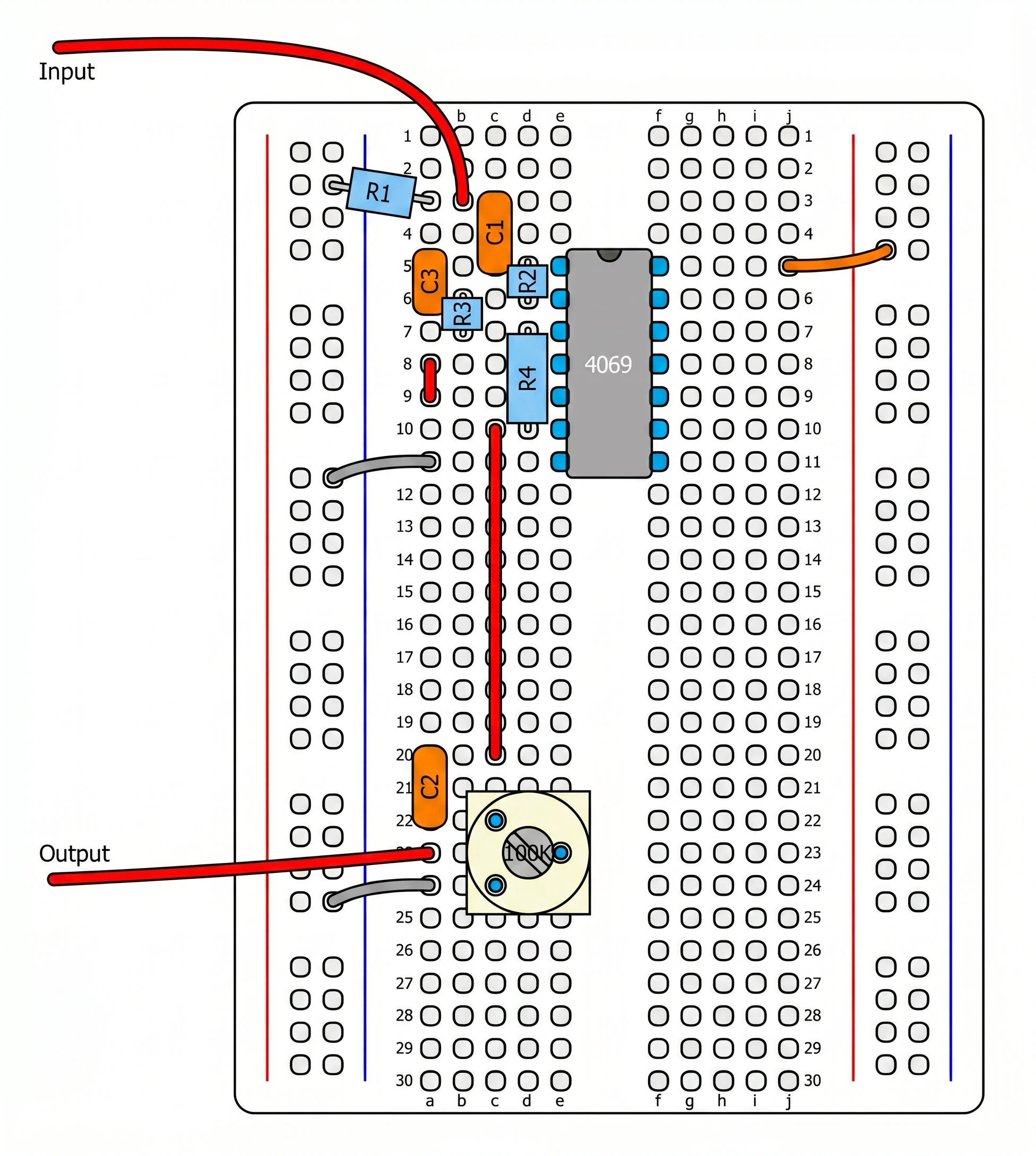
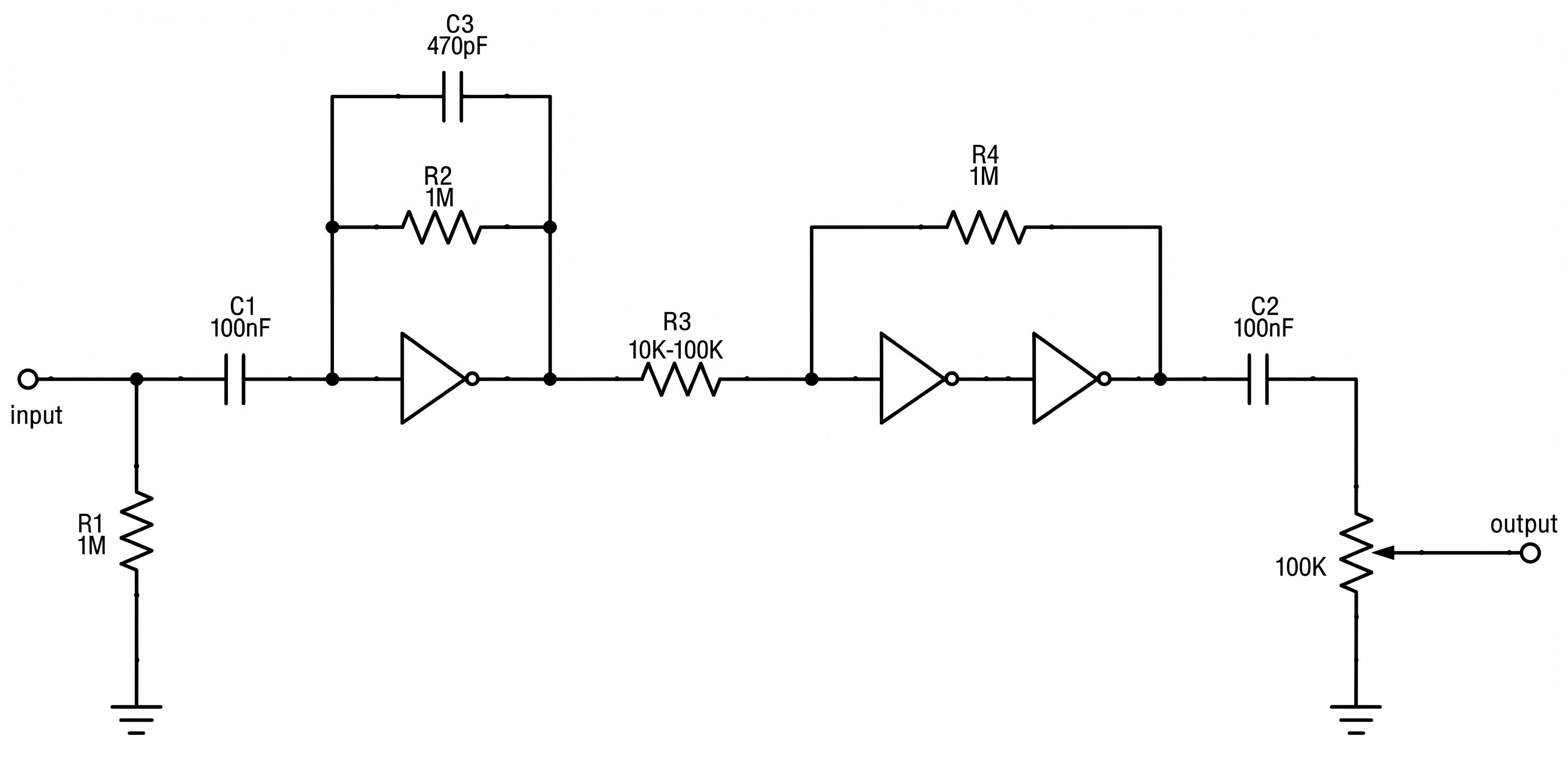
Now add R1, C1, R2, C2, and the output pot. The schematic shows what you're wiring; the breadboard photo shows where each part goes on the board. Copy the layout from the photo pin-for-pin.
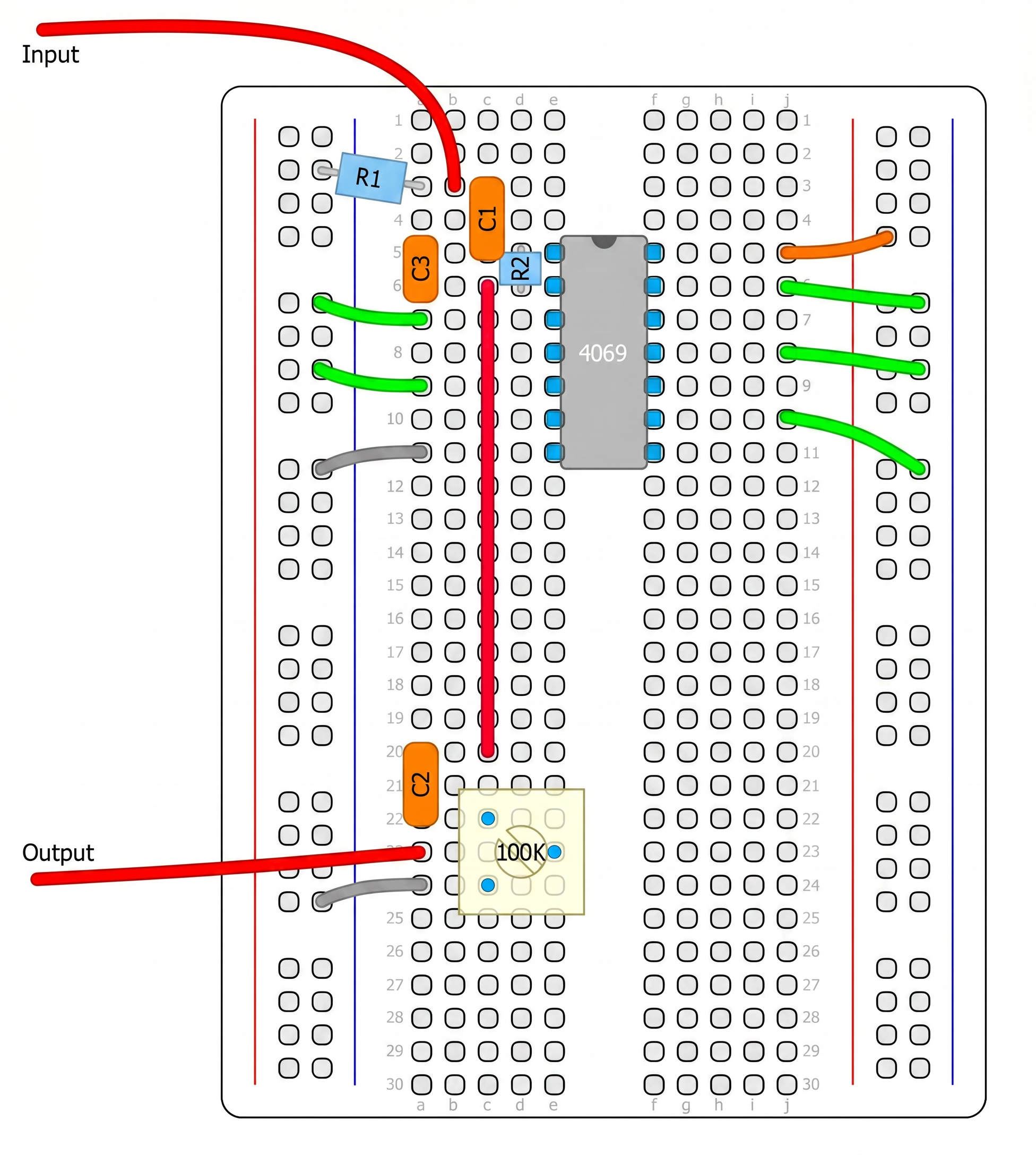
Preamp breadboard layout (Parasit Studio) — build this. R1, C1, C3, R2 clustered around pins 1-2 of the 4069; green wires ground the unused inputs; C2 + 100 kΩ pot at the output.
Power the chip: pin 14 → +9 V rail; pin 7 → GND rail. Verify VDD with a multimeter.
Ground all unused inputs (pins 3, 5, 9, 11, 13) to the GND rail. Skipping this step will cause erratic noise.
C1 (100 nF): from the input-jack tip to pin 1, the inverter input. Blocks DC from the guitar or source.
R1 (1 MΩ): from pin 1 (inverter input) to GND. Sets input impedance so the guitar sees a proper load.
R2 (1 MΩ resistor, or 1 MΩ pot wired as variable resistor): from pin 2, the inverter output, back to pin 1, the inverter input. This is the self-bias feedback and the gain control. If using a pot, connect the wiper and one outer lug together; leave the other outer lug unused.
C2 (100 nF): from pin 2 (inverter output) to one outer lug of the 100 kΩ output pot.
100 kΩ volume pot: the other outer lug → GND; the wiper → output-jack tip.
Set R2 (if using a pot) to minimum resistance — that's lowest gain, cleanest signal. Volume pot also to minimum for safety. Power on.
Gain direction: As R2 increases, the stage gets less corrective feedback and the signal gain increases, so the sound becomes louder and more distorted. Think of it like an inverting op-amp: gain ≈ R2 / Rsource. Crank R2 up, distortion comes up with it.
Optional C3: a 470 pF cap (marked 471) in parallel with R2 rolls off the top end and smooths fizzy distortion. Add it across pins 1-2 alongside R2.
Q1.
Bias check. Measure the DC voltage at pin 2 (inverter output) with no signal applied. Is it close to half the supply voltage (≈ 4.5 V)? Does it match your prediction from Part 1?
Measurement (V) + comparison
Q2.
Record clip (a) — preamp clean. Play a steady guitar note (or a 440 Hz tone from Audacity's Generate → Tone...). With R2 at minimum resistance (low gain), record a few seconds into Audacity and label it preamp-clean. Run Analyze → Plot Spectrum and screenshot.
Q3.
Record clip (b) — preamp cranked. Turn R2 up to maximum resistance for full gain. Re-record and label preamp-cranked. In Audacity, zoom in on a few cycles. Describe what's happening to the tips of the waveform at high gain.
Waveform description (zoom in, sketch or describe)
CSCM 373-01 — Fuzzbox Physics
Build the CMOS'ifier (continued)
Part 3
Build 2 — Schmitt Fuzz
Breadboard + Audacity
Goal: extend Build 1 with two more inverters plus two resistors (R3, R4) to form a Schmitt-trigger latch. Output becomes a hard rail-to-rail square wave with hysteresis — a gated, synth-style fuzz.
Keep the preamp from Part 2 in place. You'll add, not replace. Compare the new breadboard photo to the Part 2 photo — everything in the old photo is still there; the new additions are R3 (hysteresis pot feeding pin 5), the pin-6-to-pin-9 direct jumper, and R4 (feedback from pin 8 back to R3's input node).
Complete CMOS'ifier breadboard. R1, C1, R2 are the preamp from Part 2 (unchanged). R3 = hysteresis (to pin 5); Inv C (pins 5-6) → Inv D (pins 9-8); R4 (1 MΩ) = feedback from pin 8 back to the R3 input node. Output: C2 + 100 kΩ pot.
Full schematic. Preamp unchanged; R3 (10-100 k) + R4 (1 M) form the hysteresis divider around two cascaded inverters.
How the Schmitt works: R3 and R4 divide down the output voltage and mix it into the input. When the output is low, R4 pulls the input summing node down — the signal has to swing higher to cross the threshold. Once it flips, the output is high and now pulls the summing node up — the signal has to swing lower to flip back. Two thresholds instead of one = hysteresis = no chattering, clean square wave.
Rewire the output path first, then add the Schmitt components:
Disconnect C2 and the output pot from pin 2. The Schmitt goes between the preamp output and the final output stage, so these move to the end of the chain.
Remove the ground jumpers on pins 5 and 9 — those inputs are now active.
R3 (100 kΩ linear pot, wired as variable resistor — wiper + one outer lug shorted): from pin 2 (preamp output) to pin 5 (Inv C input). Start it at maximum resistance (full 100 kΩ). Parasit recommends 10-100 kΩ.
Direct jumper from pin 6 to pin 9:pin 6 (Inv C output) directly into pin 9 (Inv D input). No coupling cap — this is a DC path, we want logic behavior.
R4 (1 MΩ fixed): connect from pin 8 (Inv D output) back to the junction shared by pin 2 (preamp output) and the input side of R3. This positive-feedback path creates the hysteresis.
C2 (100 nF): from pin 8 (Inv D output) to one outer lug of the 100 kΩ output pot. Other outer lug → GND. Wiper → output-jack tip.
Double-check pins 11 and 13 are still grounded. Power on.
Q1.
Record clip (c) — Schmitt fuzz: Play a steady note and record into Audacity. Label schmitt-fuzz. Zoom in on the waveform. How is its shape different from Part 2's preamp-cranked output? How does the spectrum compare?
Observation + spectrum
Q2.
Gating. Stop playing (or let a note decay naturally). What happens to the output between notes that's different from the preamp-only version?
Observation
Q3.
Sweep R3. Rotate the hysteresis pot from max resistance to minimum. Describe how the sound changes. Where is the "sweet spot" for your pickup/input level? Did it start oscillating at the low end?
Observation
Part 4
Extra Credit — Finish Early? Try These
Optional
You used only three of the chip's six inverters for Builds 1 and 2. The remaining three are already powered and available for extension experiments. Both options below start from the completed Schmitt-fuzz build — you'll modify that circuit temporarily and can restore it afterward. Each option is worth extra credit; submit a short labeled recording and a one-paragraph write-up.
A. Cascaded CMOS Distortion ("Tube Sound Fuzz" style)
Instead of feeding the Schmitt trigger from one preamp inverter, chain two or three inverters in series first. Each stage softly rounds the peaks of the previous one, compounding into a warm, tube-like distortion. This is the circuit Craig Anderton published in Guitar Player in 1980 as the Tube Sound Fuzz — it has been copied into dozens of boutique pedals since (Way Huge Red Llama, Mu-Tron MicroV, and more).
Why it sounds warmer: one stage cranked hard produces sharp corners in the output, and those corners carry a long train of high-order harmonics — the ear reads that as "fizz." Two or three stages each kept in their soft-clip region compound the distortion without sharpening the corners, so only low-order harmonics (mostly 3rd and 5th) are added. Same amount of distortion, much warmer character. You'll see this directly in Audacity's Plot Spectrum: a long harmonic comb for single-stage-cranked, a much shorter one for three-stage-moderate.
Build A1 — two-stage preamp into the Schmitt. Cascade Inv 1 (pins 1-2, already wired) into Inv 2 (pins 3-4), then feed the Schmitt from pin 4 instead of pin 2. Low-output pickups (single-coils, vintage PAFs) benefit most — the extra stage boosts weak signals enough to sustain through the Schmitt's hysteresis.
Remove the ground jumper on pin 3.
Install a 100 nF coupling cap from pin 2 (Inv 1 output) to pin 3 (Inv 2 input). This cap blocks Inv 1's VDD/2 DC offset so Inv 2 can self-bias cleanly.
Install a 1 MΩ resistor from pin 4 (Inv 2 output) back to pin 3 (Inv 2 input). This is Inv 2's self-bias feedback.
Move the Schmitt's R3 input from pin 2 to pin 4.
Verify pin 4's DC voltage is near VDD/2 with no signal. Power up.
Record a clip labeled preamp-cascaded.
Build A2 — three-stage cascade, no Schmitt. Skip the Schmitt entirely and cascade three preamp inverters for the Anderton-style original. Uses Inv 1 (1-2), Inv 2 (3-4), Inv 5 (11-10); output from pin 10 through C2 to the volume pot. Fat, thick, sustained — try it with a bridge pickup for classic '70s rock fuzz.
Keep Inv 1 and Inv 2 from Build A1 above.
Remove the ground jumper on pin 11.
Install a 100 nF coupling cap from pin 4 (Inv 2 output) to pin 11 (Inv 5 input).
Install a 1 MΩ resistor from pin 10 (Inv 5 output) back to pin 11 (Inv 5 input).
Disconnect the Schmitt completely: re-ground pins 5, 9 (their inputs), and remove R3, R4, and the pin-6-to-pin-9 jumper.
Route pin 10 through a 100 nF cap to the output volume pot. Record as tube-sound-fuzz.
Watch out: three cascaded UB inverters at full open-loop gain have combined gain in the thousands. Stray coupling through the power rails or long jumpers can turn the whole chip into an oscillator. If you hear a steady tone between notes, either (a) shorten your jumpers, (b) add a small cap (100–470 pF) across each stage's feedback resistor to roll off ultrasonic gain, or (c) decouple VDD with a 10 μF electrolytic + 100 nF ceramic to ground right at pin 14.
EC.
Extra-credit write-up (one paragraph): Record, then compare in Audacity's Plot Spectrum: single-stage cranked (preamp-cranked from Part 2) vs. your cascaded version (preamp-cascaded or tube-sound-fuzz). At approximately the same peak level, describe what's different about the two spectra. Which has more high-order harmonics? Which sounds subjectively "warmer"? Do the two observations agree?
Comparison + spectrum screenshots
B. Tease — Where Octave-Down Comes From
Why did you spend so much effort making a square wave? Because a clean square wave is the perfect thing to feed a flip-flop — a chip that toggles its output on every rising edge of its clock input. Feed it the Schmitt's square wave and the flip-flop outputs half the frequency — one octave down.
What a CD4013 or CD4024 flip-flop does with your square-wave output.
Parasit uses the CD4013 (dual D-flip-flop — one octave per flip-flop, used in the MXR Blue Box) or the CD4024 (binary ripple counter — ÷2, ÷4, ÷8 on consecutive pins). We'll build an octave-down pedal in a later workshop. For now, the takeaway: the reason you worked so hard to make a clean square wave in Part 3 is that frequency dividers need exactly one rising edge per cycle. Noise or chatter on the square → divider mis-triggers → octave skips.
Part 5
Written Reflection
1.
The preamp and the Schmitt are both "inverters with feedback." What's the one critical difference in the feedback wiring that makes one a linear amplifier and the other a latching comparator?
Answer
2.
In one sentence, explain why the CMOS'ifier front end is the right input for an octave-down pedal but the wrong input for a clean reverb.
Answer
3.
Open fuzzbox-cmos.html and listen to both the CMOS Preamp and Schmitt Fuzz topologies. Do they sound like what you just built? One-sentence comparison.